BR-PV-SED Sharpness of Edge Determination Equipment
Implementation of standards: UL 1703-2008, UL 1439-2004
Edges, projections, and corners of photovoltaic modules and panels shall be such as to reduce the risk of injury to persons.
Whenever a referee measurement is necessary to determine that a part as mentioned in 6.9 is not sufficiently sharp to constitute a risk of injury to persons, the method described in the requirements in the standard for Determination of Sharpness of Edges on Equipment, UL 1439, is to be employed. The test apparatus is to consist of the following:
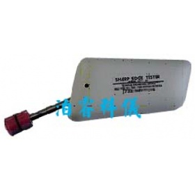
a) Sharp-Edge Tester The instrument consists essentially of a handle with a pivoted arm attached. A constant-tension spring secured to the handle is used to apply a steady force to the arm. The arm head is a piece of round steel, with an outside diameter of 12.7mm located at the end of the adjustable arm. The arm head is to be wrapped with three layers of tape, the two outer layers act as sensing tapes; the inner layer acts as an indicating tape, or the tapes are to be applied to a 15.9mm removable sleeve that is placed onto the 12.7mm steel head.
b) Indicating Tape (Inner Layer) 19.1mm wide, adhesive backed, single-adhesive coated, vinyl foam tape, black in color, having the tape properties given in Table 5.1.
c) Sensing Tape No. 2 (Middle Layer) 19.1mm wide, double-adhesive coated, vinyl foam tape, white in color, having the tape properties given in Table 5.1.
d) Sensing Tape No. 1 (Outer Layer) 19.1mm wide, single-adhesive coated skived tetrafluorethylene tape natural color, having the tape properties given in Table 5.1. The skived tetrafluorethylene backing (film) is shaved in a thin layer from a cylindrical block of material.
e) Calibration Equipment A weight that can exert 6.7N and a length of string.
Test Procedure:
The curved face of the tester head shall be covered with three layers of tape in the order indicated below:
a) First Layer (Inner Layer) Indicating type, black vinyl foam tape as described in 5.1 (b).
b) Second Layer (Middle Layer) Sensing Tape No.2, white vinyl foam tape as described in 5.1(c).
c) Third Layer (Outer Layer) Sensing Tape No.1, tetrafluorethylene tape as described in 5.1 (d). Each tape is to be applied over approximately 180 degrees of the circumference of the test head to prevent stretching of the tape.
The tapes are not to be stretched when positioned on the head.
The center of the tape-covered head of the sharp-edge tester shall be positioned on the edge to be tested in the manner illustrated in Figure 7.2. The arm of the tester shall be between stops so that the tape-covered head exerts a 6.7N on the edge. The tester shall be immediately moved along the edge a distance of 50.8mm and then back to its starting position without removal of the tester from the edge. It shall then be withdrawn from the edge. The total distance of engagement between the edge and the tape-covered head is not to exceed 101mm. The time of travel is not to take longer than 5 seconds nor less than 2 seconds.
Exception: An edge less than 50.8mm long shall be tested for a distance of twice its length.
(Example: For an edge 1-1/2 inches or 41.2 mm long, the tester is to be moved along its length and back to the starting position so that the total distance of engagement between the edge and tester is 3 inches or 76.2 mm).
上海泊睿科学仪器有限公司
仪器网(yiqi.com)--仪器行业网络宣传传媒
